From Display Primaries to “virtual” Primaries
In the last part I tried to explore Rec.2020, but as I cannot view any image due to the lack of an available display, I take some steps back again to the sRGB image of the “Red Star on Cyan”. This image should be displayed on nearly every display properly.

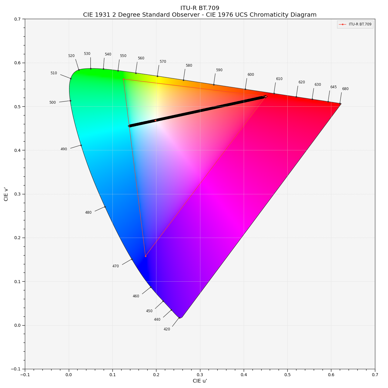
Is there something beyond Rec.2020? Entering the working colorspace ACEScg.
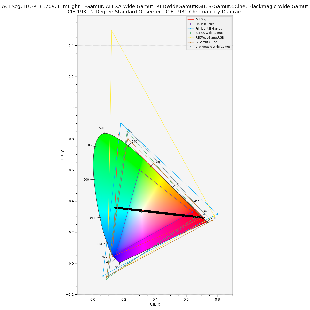
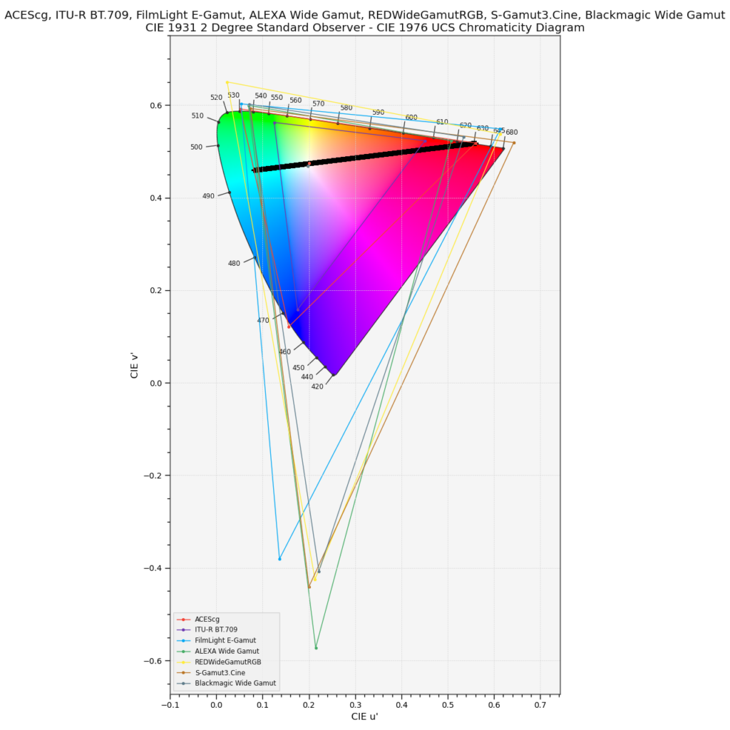
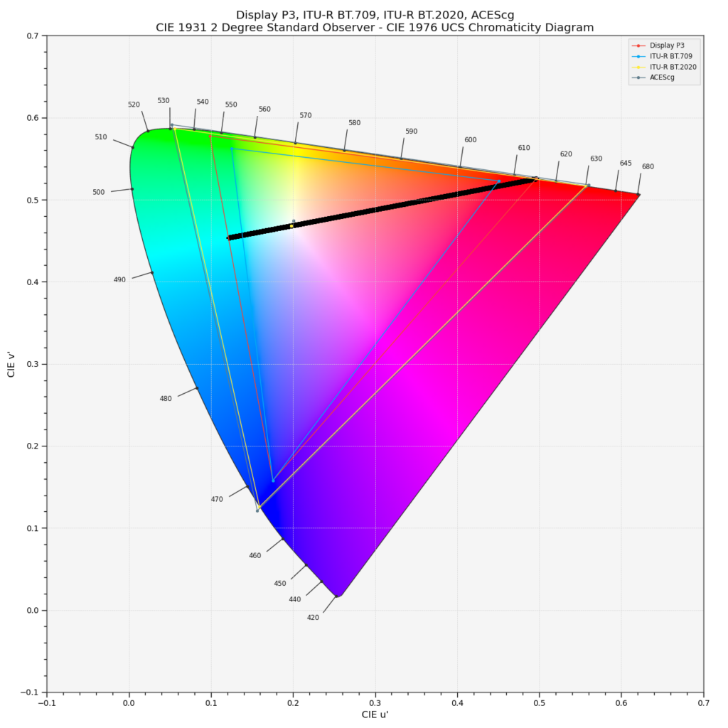
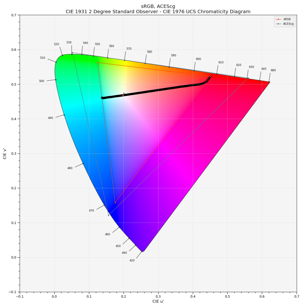
The following diagram shows again a plot from a “Red Star on Cyan” image like the one above, but this time I added another working colorspace called ACEScg. If you look closely, you can see that the gamut of ACEScg is even bigger than the display gamut of Rec.2020. The primaries of Rec.2020 are defined by a single wavelength of light, in other words you need a laser source to reproduce them. If ACEScg is positioning their primaries outside the spectral locus, the cannot refer to any visible sensation that a human can experience, right? I mean not before getting back to a sensible display colorspace.
Virtual primaries can be tricky
When I first saw the Red Star on Cyan example on the blog from Troy Sobotka (mentioned in part 1), I thought I am safe in the assumption that ACES with its working colorspace ACEScg will handle this image with ease when I don’t exceed the ACEScg primaries. But I was proven wrong. Since then I wondered and investigated why. This lead in the end to this series of articles of the “Red Star on Cyan”. But instead of looking from the working colorspace to the display output, I started at the output medium, the display and worked my way up from a typical sRGB display to Display-P3 and Rec.2020 (at least in theory).
I am using ACEScg as a working colorspace for some years now at work. In my job I use ACES/OCIO on a daily basis with high dynamic range imagery from professional cameras and from 3D renderings. A lot of the things that I learned by using ACES I wrote down in the two sections: Learning ACES and (hopefully) Understanding ACES.
The ACEScg primaries are virtual, a mathematical construct. Some grading applications like Resolve and Baselight use virtual primaries as their working colorspace. And camera manufacturer such as ARRI, RED, Blackmagic, Sony etc. are using 3D-Lut’s that could expect virtual primaries as well.
Trying out the “Red Star on Cyan” in ACEScg
It’s time to try out the Red Star on Cyan image using ACEScg primaries. The ACEScg red primary lies outside the spectral locus, whereas the cyan mixed value that is created out of the ACEScg green and blue primary fall inside the spectral locus.
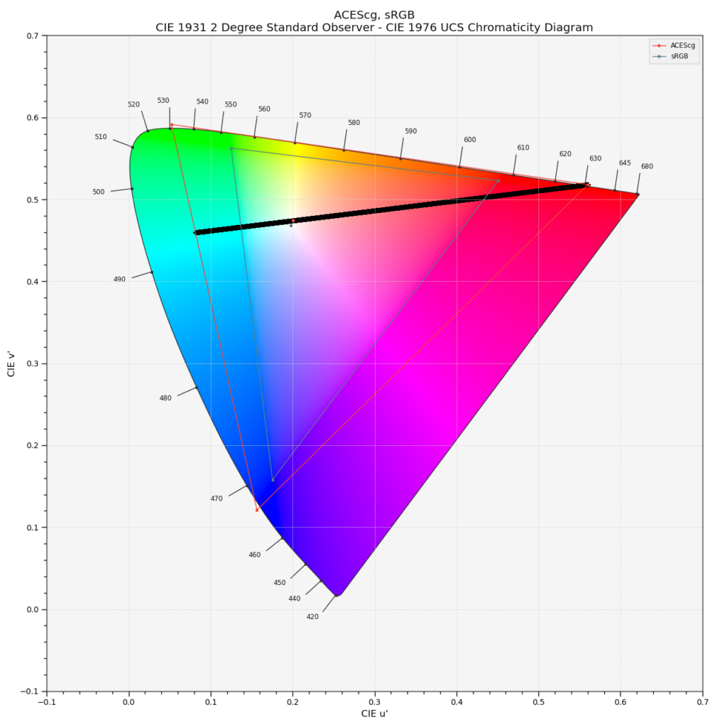
How can I display such an “image”? In all the examples that I showed and plotted before, there was a direct relation between the display primaries and the image data. I simply assigned the maximum values of the image data to a set of display primaries, encoded the data for a specific display and viewed the images on my available screens. This worked well for the primaries of sRGB and Display P3, but it failed with Rec.2020, because I don’t have a laser primaries display at my disposal.
The “real” Rec.2020 primaries are very close to the virtual ACEScg primaries. So the best change to view this image would be by using a Rec.2020 ODT and view the resulting image on a laser display. ACES RRT& ODT’s are “rotating” and “transforming” the working space primaries to the selected display primaries. As the Rec.2020 gamut is smaller than the ACEScg gamut, the display rendering transform for a Rec.2020 display would cut off the values that fall outside the Rec.2020 gamut. I can only assume how this image would look like, but I guess this would be a pretty intense image to look at.
Already the Display P3 HDR version with 1.000 nits of brightness that I showed in part 2 was a very intense image to look at.
I have “only” sRGB and Display P3 screens available to me. So how can I “render” the ACEScg primaries and make them fit into the much smaller sRGB gamut boundary?
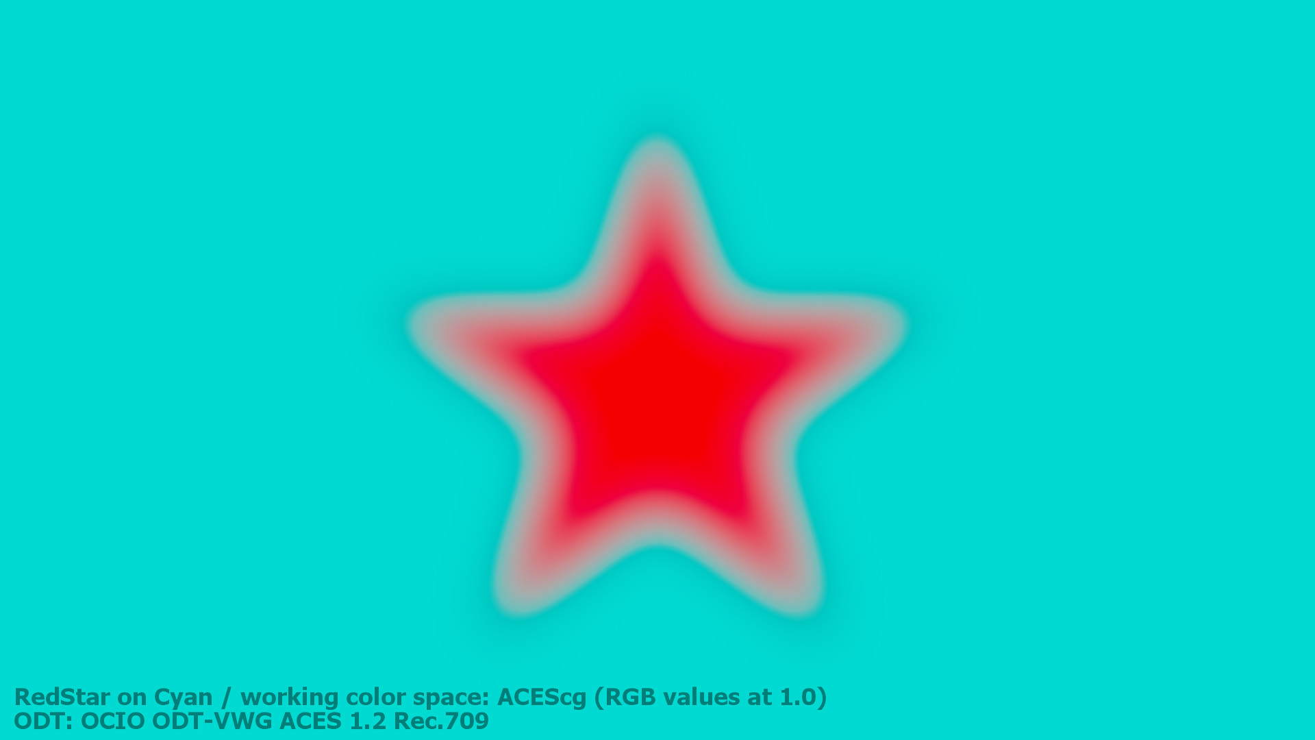
I need to chose the sRGB ODT to render the image for any standard sRGB display. The following plot shows the result of the sRGB ODT and what the display is forced to show. There is a small kink at the gamut boundary for cyan visible and a heavy bend close to the red primary. The plot is not a straight line and this is visible in the resulting image.

And the image looks broken again. Similar to the Rec.2020 example from the last page in part 3.
A summary from the beginning to this point.


This is a summary of the results from the last parts of this blog post series: (read from top left to bottom down)
- A: The inverse EOTF step is ignored in a lot of graphic programs and apps. The display hardware applies the EOTF and the image looks wrong and broken.
- B: The same composting steps as in example A, but the inverse EOTF is applied before viewing or saving the image. The inverse EOTF and the EOTF cancel each other out and I am presented a with a proper result on my typical sRGB display.
- C: Exactly the same compositing setup as in B, but this time the working space is set and tagged as Display P3. The red and cyan colors show the maximum intensity possible for a Display P3 screen.
- D: Again the same comp setup, this time the working space is set and tagged as Rec.2020. Apple’s ColorSync is recognising the Rec.2020 tag and “knows” that my Display can show maximum Display P3 colors. The biggest display gamut to date gets compressed to Display P3 and artefacts appear. Theoretically this image should look fine when viewed with on a Rec.2020 laser projector.
- E: And for the last time: the same comp setup is used from A to E. The slightly bigger ACEScg gamut with it’s virtual primaries that are larger than Rec.2020 and outside the spectral locus get transformed to the sRGB primaries. All the values outside the sRGB gamut are clipped off. The ACES RRT tone mapping maps the value 1.0 to a lower value for the display, therefore the resulting image is darker than all the other examples. ACES 1.3 provides a “reference gamut compress” function, but it only tackles values outside the gamut of ACEScg (AP1). The values I used for this image example are ACEScg primaries and therefore gamut compress function does not do anything.
Ways to improve image E
With the knowledge that the ACES RRT&ODT clamps all values outside the display gamut, a simple and NOT very helpful fix for this image example is simply not using primaries larger than the display gamut. It kind of works, but it defies the idea of a big working space gamut in the first place. Because this would mean you would need to adjust the red and cyan colors for each target display manually. This is not a Color management, it is missing a gamut mapping functionality.
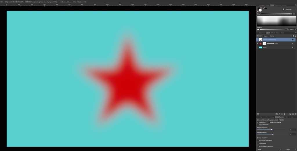
To illustrate the example I took image B in Affinity Photo in a 32-bit document that uses the ICC Display Transform. As the image looks right the Display Transform includes the inverse EOTF.
As soon as I switch to the OCIO Display Transform for “sRGB” I see again image E: The sRGB display primaries are now assumed to be ACEScg primaries. To properly convert the sRGB primaries into the ACEScg working colourspace I chose the command “Document Convert Format / Convert ICC Profile” and choose ACEScg.
The resulting image looks better but not completely right. So what happened with the last command? The conversion from sRGB to ACEScg transformed the pixel values from 1/0/0 and 1/1/0 to some smaller values. This means, when a sRGB ODT is used, the values refer again to the maximum possible emission of a sRGB display. The image looks kind of correct, but this limits my ability to work only with values that do not exceed the display primaries of my selected ODT.
The last image above I could call now:
- F: ACEScg working space, but limited to sRGB with the display transform for sRGB.
Looking for alternative Display Transforms
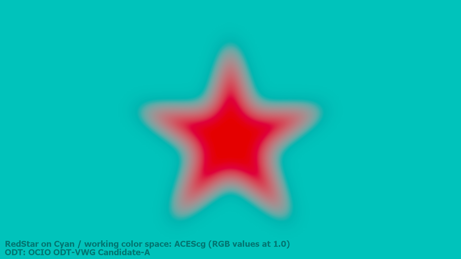
For about a year I follow the efforts of a virtual working group to come up with a revised RRT&ODT for ACES 2.0 on ACESCentral.com. There will be a test package available soon. I checked out the a preview test package in Nuke via a special OCIO config. In Nuke I rendered out the Red Star on Cyan with ACEScg primaries through the existing ACES 1.2 SDR transform as well as three candidates that are are up for discussion at the moment. The candidates will most likely change before they get released one day. Candidate C does do a better job with this rather unusual image example, but there is still a slight dark halo visible.
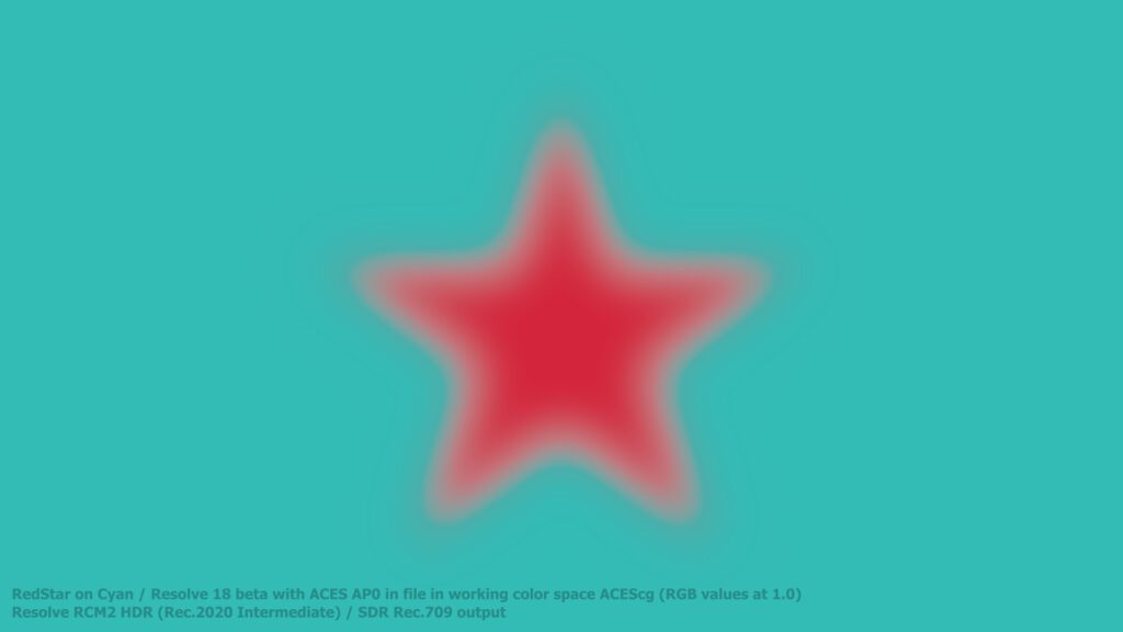
And at last here is the ACEScg primaries EXR file saved in AP-0 (ACES 2065-1) and viewed in Resolve 18 Beta5 through their RCM2 pipeline. As far as I can see the HDR processing and SDR viewing preset uses a “Rec.2020 Intermediate working colourspace” and the standard Rec.709 EOTF. The colours are even more dull but the blurred star has a smoother gradient than the standard ACES 1.2 ODT. Still there is also here a dark halo visible.
Conclusion: More questions than answers
Wide gamut and HDR displays are getting more and more common. And the graphics, 3D, compositing and grading applications get support for new colour workflows. We always work with pixel values (numbers) and these have a meaning for the processing chain up to the display. And depending on the selected workflow these numbers will have a different meaning.
The “red” constant that created the red star with a mask in Nuke has a value of 1.0 for all the examples in the whole series of these 4 blog posts. Depending on the working colourspace and the transfer function it means maximum red emission from a sRGB, a Display P3, in theory a Rec.2020 display.
As soon as we enter working colourspaces with virtual primaries and open domain image states it is a whole different game.
I hope this brings the “Red Star on Cyan series” to an end for now as it took me a year and a half to finish all four parts.

